The current article dedicated to the presentation of a little PowerShell script that I have…
Client protocol connectivity flow in Exchange 2013/2010 coexistence | Introduction and basic concepts| 1/4 | 20#23
To be able to understand the different “Exchange clients” connectivity protocol flow in Exchange 2013/2010 coexistence environment, we will review five types of “relationships” that exist between Exchange 2010 client and the Exchange CAS 2013 server:
- Autodiscover client – protocol connectivity flow (Part 2#4)
- Outlook client – protocol connectivity flow (Part 2#4)
- OWA client – protocol connectivity flow (Part 3#4)
- ActiveSync client – protocol connectivity flow (Part 4#4)
- Exchange web service client – protocol connectivity flow (Part 4#4)
Table of contents
- Exchange 2010 client protocol connectivity flow road map
- Exchange coexistence environment | Scenario infrastructure and charter’s description
- Public Exchange Infrastructure | The concept of main\primary Public facing Exchange site | Autodiscover Endpoint
- The “primary Public facing Exchange CAS” and Autodiscover services
- Organization Namespace and Exchange infrastructure
- Exchange 2013 CAS as a starting point and as a “Smart router” for external Exchange clients
- Client protocol connectivity flow | Scenario’s matrix
General terms that we will be used along the current article series.
- Exchange 2010 client – when we mention the term: Exchange 2010 client, the meaning is Exchange client that his mailbox hosted on the Exchange 2010 mailbox server.
- Exchange CAS 2013 or CAS2013 or “New York Public facing Exchange CAS” – in our scenario, the Exchange 2013 coexistence environment is implemented by adding Exchange CAS 2013 infrastructure to the headquarter company: the New York site. The “New York Exchange 2013 CAS server” will serve as the main point or focal point for external Exchange client and internal Exchange clients as an: Autodiscover Endpoint.
Exchange 2010 client protocol connectivity flow road map
One of the main charters of Exchange 2013 coexistence environment, is the “abundance” of a different mail client protocol, different Exchange services and so on.
To be able to “digest” this complex infrastructure, we need to use some logical structure that will help us arrange all the different parts.
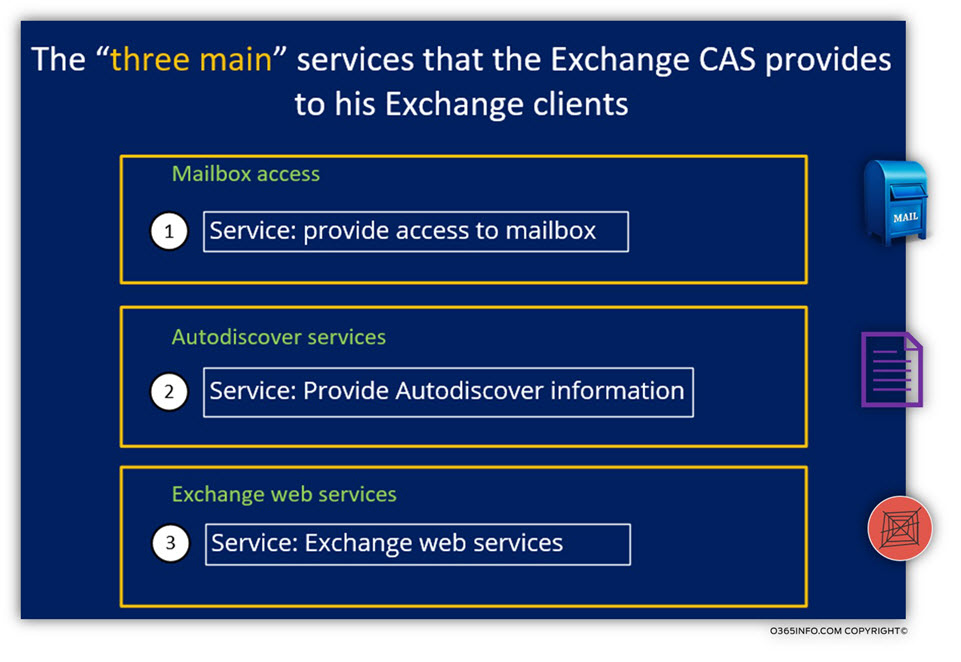
To clarify the essence of the “relationships,” between the Exchange 2013 CAS server and his Exchange 2010 clients, we can define three primary responsibilities of Exchange 2013 CAS server to his Exchange 2010 clients (and Exchange 2013 clients).
We can classify the responsibilities of Exchange CAS to his Exchange client into two major sections:
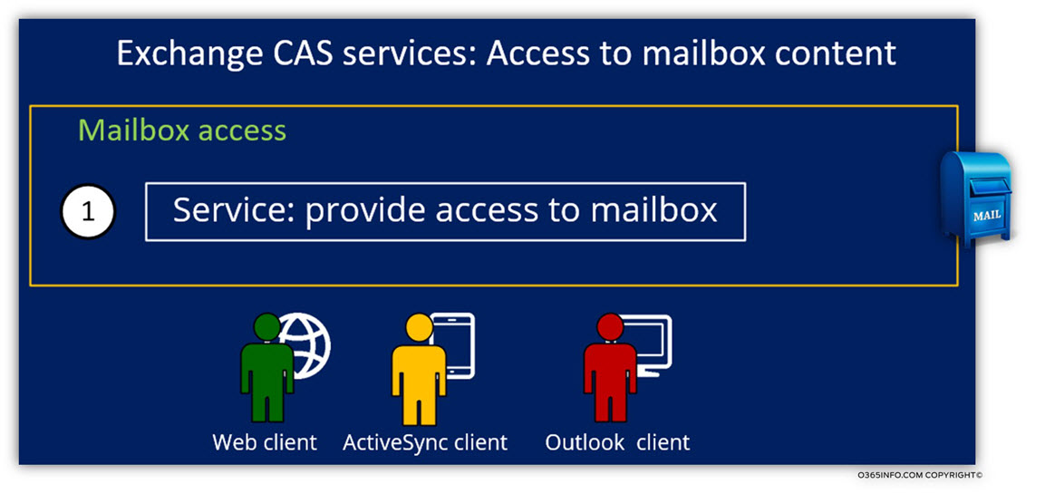
Section 1: providing access to a user’s mailbox
The most basic and essential service that Exchange 2013 CAS provides to his Exchange clients (legacy or non-legacy Exchange client) is the ability to get access to the content of their mailbox.
In an Exchange environment, the only way that Exchange client can use for access Exchange mailbox content is, by addressing the Exchange CAS server, which will “handle his request” and “mediate” between the Exchange mail client and his Exchange Mailbox server (in our scenario, the mailbox that is hosted by Exchange 2010 Mailbox server).
To be more specific about the term: “providing mailbox access”, in an Exchange 2013 coexistence environment, the Exchange CAS server is responsible for providing mailbox access to three different types of mail clients:
- Webmail client (OWA)
- ActiveSync mail client (Mobile)
- Outlook mail client
Section 2: Autodiscover services
The Autodiscover services
- Point Exchange client (provide information) to existing Exchange web services such as: Free\Busy time and so on.
- Provide Outlook client the required configuration setting needed for creating a new mail profile and for the ongoing communication with Exchange server.
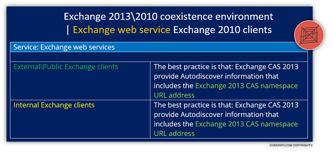
Section 3: Exchange web services
In Exchange 2013/2010 coexistence environment, the element that provides Exchange web services to Exchange 2010 clients is the Exchange 2013 CAS server.
Exchange 2010 clients will contact Exchange CAS 2013 by default and the “Behind the Scenes” the Exchange CAS 2013 will “fetch” the Autodiscover information from an Exchange CAS 2010 server.
1. Exchange CAS server | Providing Exchange mail client access to their mailboxes.
Each of the Exchange mail clients, have a unique and specific charter. For this reason, each of these “mail clients” has different relationships with the Exchange CAS 2013 or in other words: the client protocol connectivity flow for each of these Exchange mail clients is implemented differently.
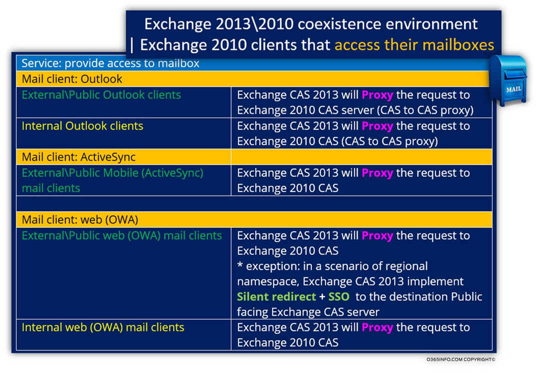
In Exchange 2013/2010 coexistence environment, the “task” of enabling Exchange 2010 client’s access to their mailboxes, will be implemented by default by using the “Proxy” method.
When Exchange 2010 clients such as Outlook, ActiveSync or OWA addresses the Exchange 2013 CAS, asking access to their mailbox, the Exchange 2013 CAS will proxy their request to Exchange 2010 CAS.
An exception to the “default Proxy” rule, is implemented in a scenario which described as:” Exchange OWA client and a multiple Public facing Exchange site environment. In this scenario, the Exchange CAS 2013 will use the method of redirecting instead of “Proxy”. You can read more information about this scenario in the article: OWA client protocol connectivity flow in Exchange 2013/2010 coexistence environment | 3/4
Note: The method of redirecting the OWA client in a scenario of “multiple Public facing Exchange site environment” is not related only to “Exchange 2010 OWA client” but to any external Exchange OWA client.
In the following diagram, we can see a summary of the Exchange client protocol connectivity flow that is implemented in Exchange 2013/2010 coexistence environment when the Exchange 2010 client requests access to their “Exchange 2010 mailbox.”
Exchange 2010 clients will access their mailboxes that hosted on the Exchange 2010 mailbox server via the “mediation” of Exchange CAS 2013 server. In other words, Exchange 2013 CAS will proxy all of the Exchange 2010 clients to the “legacy Exchange infrastructure” (Exchange CAS 2010).
2. Exchange server as an Autodiscover provider
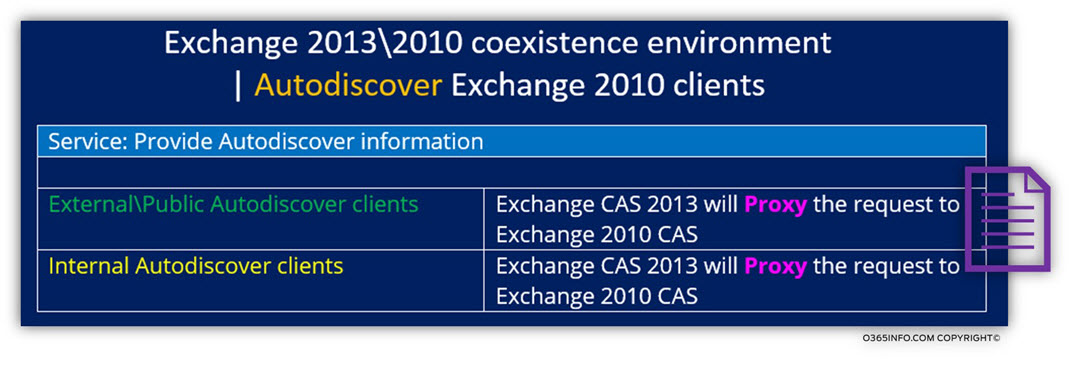
In an Exchange 2013/2010 coexistence environment, the Exchange CAS 2013 server act as an “Autodiscover focal point” for all the types of Exchange clients: native Exchange clients (Exchange 2013) and legacy Exchange (Exchange 2010) clients.
When Exchange 2010 clients address Exchange 2013 CAS, requesting for Autodiscover information, the Exchange 2013 CAS handles the request by “forward” (Proxy) the Autodiscover requests, to the Exchange 2010 CAS.
The element that generates the Autodiscover information is the Exchange 2010 CAS and the element the “physically” provide the Autodiscover information to the Exchange 2010 clients is, the Exchange 2013 CAS.
To recap:
- Exchange 2010 clients will address the Exchange CAS 2013 server when they need Autodiscover information. In other words, Exchange 2010 clients relate to the Exchange 2013 CAS as: Autodiscover Endpoint.
- Exchange CAS server proxy the requests to Exchange 2010 CAS.
- The Exchange 2010 CAS generates the Autodiscover response.
3. Exchange server and Exchange web services
The third part relates to the Exchange web services.
In Exchange 2013/2010 coexistence environment, the preferred method or the best practice is: that the Exchange 2013 CAS, will provide Exchange web services to Exchange 2010 clients.
Exchange coexistence environment | Scenario infrastructure and charter’s description
In the next three articles, we will review a couple of possible scenarios of: Exchange 2010 client protocol connectivity flows in Exchange 2013/2010 coexistence environment.
The organizational infrastructure that will use for demonstrating the possible protocol connectivity flow, has the following characters:
Geographical infrastructure disruption
o365info, is a global company that has three sites:
Two sites in the USA and one site in Europe.
1. Public facing Exchange site
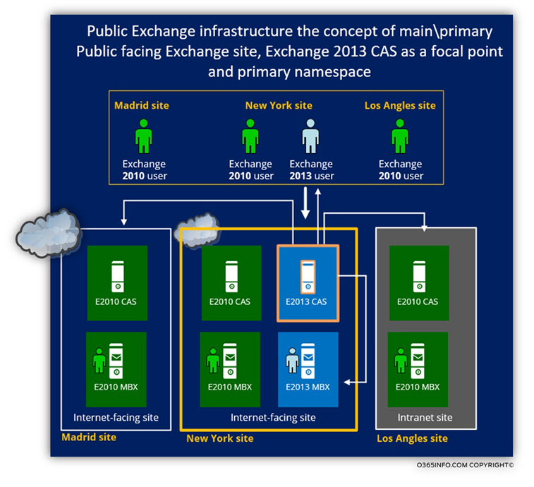
The company headquarters site located in New York and the additional sites are Los Angles and the Madrid site.
New York and the Madrid site are: “Internet facing sites”.
- The New York site includes Exchange 2013 Public facing server.
- The Madrid site includes Exchange 2010 Public facing server.
2. Non-Public facing Exchange site
The Los Angles site configured as an intranet site. The meaning is that the “Los Angles internal Exchange infrastructure is not “exposed” to public Exchange clients.
The Los Angles Exchange user does not have the ability the “direct access” their Exchange infrastructure, but instead, they will need to use the “New York Public facing Exchange CAS” as a “Mediator” or a “Broker” that will help them to access the “internal Los Angles” Exchange infrastructure.
In a scenario, in which an “external Los Angles Exchange users” need to access his mailbox, the user will address the “New York Public facing Exchange CAS” and use “his help” to get to his mailbox.
The “New York Public facing Exchange CAS” will accept the Los Angles external Exchange clients and, Proxy these requests to the internal Los Angles Exchange infrastructure.
Public Exchange Infrastructure | The concept of main\primary Public facing Exchange site | Autodiscover Endpoint
Although Exchange public infrastructure can be distributed between many Public facing Exchange sites and, use many different namespaces, the “logical infrastructure” of the Exchange public environment will be based most of the time, on a model which can describe as a “centralized model”.
The meaning of this “centralized model” concept is that all the Exchange clients, will start their “journey” by connecting or addressing a specific “focal point” and this “focal point” will decide how to “promote” the Exchange client request.
In a public Exchange environment, the meaning of “focal point” translates into the concept of public Autodiscover Endpoint.
As mentioned, even in a scenario in which the organization infrastructure consists of multiple Public facing Exchange sites, the Autodiscover Endpoint will point only to one “element” and the client protocol connectivity flow, will be “determined,” based on the information that is provided by this “primary Autodiscover Endpoint.”
Note: The descriptive concept of: “primary Public Autodiscover Endpoint” is implemented most of the time, but, there are other alternatives to this method. For example, in a modern network environment, there is an option for using GeoDNS which enable to implement a different that could be described as a “distributed model” (vs. the “standard centralized model).
In a solution that is based on GeoDNS, the AutoDiscover public record such as: autodiscover.o365info.com, will be pointed to a couple of Public facing Exchange site at the same time. The element that will “direct” client to the “right Autodiscover Endpoint” is the GeoDNS server.
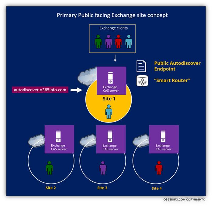
To demonstrate the concept of: “major Public facing Exchange site”, that holds the role of public Autodiscover Endpoint, let’s use the following scenario:
The “primary Public facing Exchange CAS” and Autodiscover services
An organization that has four Public facing Exchange sites. Although there are four Exchange sites with “Public availability “and although each site has a: Public facing Exchange CAS server, only one site will be considered a “primary Public is facing Exchange site.” In our scenario the Autodiscover record: autodiscover.o365info.com is pointing to the Public facing Exchange CAS server in site 1.
In the following diagram, we can see that external Exchange clients from all the different Exchange sites, start the communication process with the Public facing Exchange CAS server in site 1. Because the public Autodiscover record is “mapped” to the IP address of the Public facing Exchange CAS server from site 1.
- In case that the external Exchange client “belong” to site 1, the Public facing Exchange CAS server sends Autodiscover information that includes information about public Exchange resources from site 1.
- In case that the external Exchange client “belong” to site 2, the Public facing Exchange CAS server sends Autodiscover information that includes information about public Exchange resources from site 2 and so on.
The “primary Public facing Exchange CAS” and access to mailbox data services
In a scenario that the external Exchange client needs access to his mailbox, the Public facing Exchange CAS server from site one that serves until now, as: “public Autodiscover Endpoint”, start to act as a “Smart Router” that handles the Exchange client requests for mailbox access.
Scenario 1: In case that the external Exchange client “belong” to site 1, the Public facing Exchange CAS server will proxy the external Exchange client request to the “internal Exchange infrastructure.”
In case that the external Exchange client “belong” to site 2, there are a couple of possible scenarios.
Scenario 1: In case the “Exchange client from site 2” is an: Outlook client, the external Outlook client will contact the “public representative” of “his site” such as the Public facing Exchange CAS server of site 2 (based upon the Autodiscover information that he got in the previous phase).
Scenario 2: In case the “Exchange client from site 2” is ActiveSync client, the “New York Public facing Exchange CAS” will Proxy the client request to the “Madrid Public facing Exchange CAS.”
Scenario 3: In case the “Exchange client from site 2” is OWA client, the “New York Public facing Exchange CAS” will send a redirection command to the OWA client that will redirect the OWA client browser to the “Madrid Public facing Exchange CAS”.
In the following diagram, we can see the process in which the “New York Public facing
Exchange CAS” accepts the external Exchange client communication request and, based on the type and the Exchange CAS server location, decide how to handle the request.
Organization Namespace and Exchange infrastructure
In an Exchange 2013/2010 coexistence environment, we can relate to a couple of “namespace infrastructures”:
- External\Public namespace infrastructure – this is the namespace that used for publishing Exchange hosts who have Public availability (can be accessed by external Exchange clients)
- Primary namespace infrastructure – the “translation” of the “central concept” is the Exchange CAS server who will serve as a “focal Autodiscover Endpoint”
- Internal namespace infrastructure – this is the namespace infrastructure that is “not exposed” to the public network and can be used only by the internal Exchange client. The internal Exchange namespace could be different from the external namespace this scenario described as a disjoint namespace. In our particular situation, the internal and the external namespaces are identical.
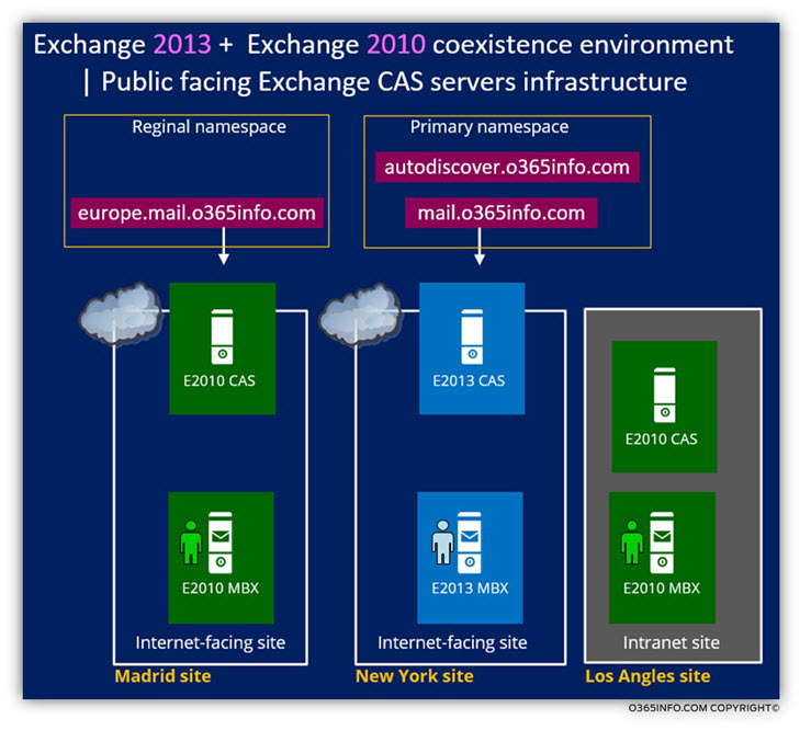
In our scenario, we will be based on two namespaces:
- Primary namespace – the main namespace points to the “Exchange 2013 New York Public facing Exchange CAS server”
- Regional namespace – the regional namespace, points to the “Exchange 2010 Madrid Public facing Exchange CAS server”
Before the implementation of the Exchange 2013 coexistence environment, the representative of the “New York Public facing Exchange site” was Exchange CAS 2010. After the implementation of the Exchange 2013 coexistence environment, which includes: adding Exchange 2013 servers to the company headquarter site (New York site), the Exchange CAS 2013, will replace the previous Exchange CAS 2010 that configured as the Public facing Exchange CAS server.
In our scenario, the primary namespace will be “attached” to the “New York Public facing Exchange 2013 CAS server.”
The Exchange public infrastructure will include the following public DNS records:
- Primary namespace that includes two DNS records that point to the “New York Public facing Exchange CAS server”:
- Autodiscover record: autodiscover.o365info.com
- FQDN name for all the rest of the Exchange services: mail.o365info.com
- Regional namespace – The Madrid Public facing Exchange site will continue to use Exchange CAS 2010 as a Public facing Exchange CAS server. The “Madrid Public facing Exchange 20007 CAS server” “published by using the public DNS records using the Regional namespace: europe.mail.o365info.com
Exchange 2013 CAS as a starting point and as a “Smart router” for external Exchange clients
In an Exchange public environment, the Public facing Exchange CAS server who acts as the Autodiscover Endpoint for an external Exchange client, holds a very essential part in the Exchange client protocol connectivity flow because, all the “flows” will start from a specific point – the public Autodiscover Endpoint.
Phase 1: Exchange 2013 CAS as central Autodiscover Endpoint
Because the Exchange 2013 CAS configured as the Autodiscover Endpoint, all the “Exchange client flows” will start from this particular Exchange server,
All the external Exchange clients will start their Initial communication process with the “New York Public facing Exchange CAS” by relating to the “New York Public facing Exchange CAS” as the source of information or in more technical words: Autodiscover Endpoint.
The same “Autodiscover logic” is also implemented to toward internal Exchange client and two different types of Exchange client such as Exchange 2010 clients and Exchange 2013 clients.
The information that the “New York Public facing Exchange CAS” will provide to the external Exchange client and the continuation of the client protocol connectivity flow will depend on the physical location of the external Exchange client mailbox.
Phase 2: Exchange 2013 as a “Smart Router”
The second “Title” of the Exchange 2013 CAS after he fulfills his job as a “central Autodiscover Endpoint” is to serve as a “Smart, Router,” that will handle the external Exchange mail client requests and, based on the unique charters of the scenario, choose the best “next step”.
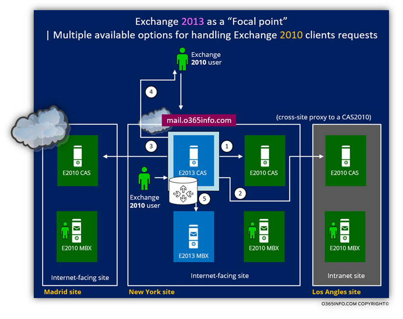
In the following diagram, we can see an example of the different methods, which the Exchange 2013 CAS can choose when he gets a “connection\service requests” from external and internal Exchange 2010 clients.
In the following diagram, we can see an example of the different methods, which the Exchange 2013 CAS can choose when he gets a “connection\service requests” from external and internal Exchange 2010 clients.
The Exchange 2013 CAS can choose one of the following methods for serving the Exchange clients:
- Exchange 2013 CAS can choose to proxy the request to: a local Exchange 2010 CAS such as in a scenario that Exchange client 2010 Outlook and ActiveSync need access to their mailbox (Number 1).
- Exchange 2013 CAS can choose the proxy to the request to: “remote Exchange 2010 CAS” that is located on a different Active Directory site. This operation described as: cross site proxy (Number 2 + 3).
- Exchange 2013 CAS can choose a combination” of methods such as: send a redirection command to the external OWA client + Proxy the user credentials to Exchange 2010 CAS, in a scenario of an OWA client and regional namespace (Number 4).
- Exchange 2013 CAS can choose to proxy the request to Exchange 2013 Mailbox server in a scenario of Exchange 2013 client that needs access to his mailbox (Number 5).
Client protocol connectivity flow | Scenario’s matrix
One of the most confusing subjects of Exchange 2013/2010 coexistence environment, is something that I describe as: “client protocol connectivity flow – the scenario’s matrix infrastructure”
I use the term: ”Matrix” because, in a complex Exchange environment, the number of the client protocol connectivity flow scenarios could be huge.
To be able to make it more “digestible”, we can reduce the optional client protocol connectivity flow situation, into to six above scenarios.
The “six major scenes” can be divided into two groups:
1. External Exchange 2010 client’s possible scenarios
In the following diagram, we can see the three major optional scenarios, for External Exchange 2010 client’s in an Exchange 2013/2010 coexistence environment.
The common denominator for all the different scenarios is that the “journey” of the Exchange 2010 clients, begins at the Public facing Exchange CAS server of New York site.
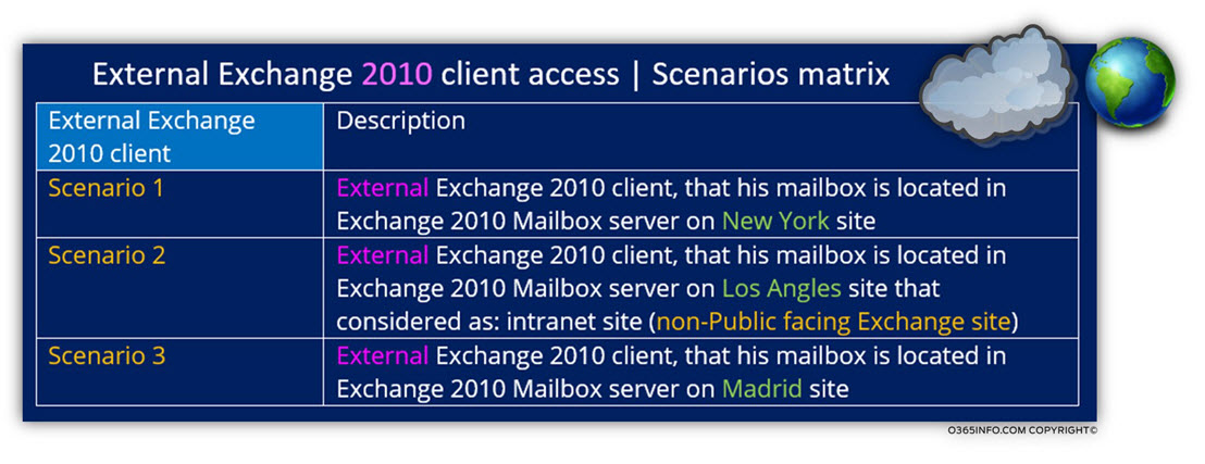
The rest of the flow depends on upon the location of the Exchange 2010 Mailbox server which hosts the user mailbox.
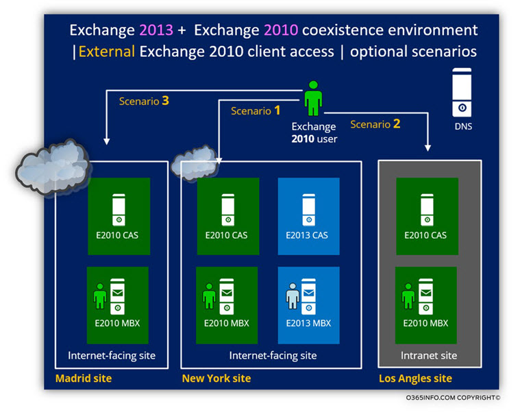
Scenario 1 – Exchange 2010 user, which his mailbox hosted on Exchange 2010 Mailbox server at the New York site.
The “New York Public facing Exchange CAS server” will handle the external Exchange 2010 by – Proxy his request to the internal Exchange CAS 2010.
Scenario 2 – Exchange 2010 user, which his mailbox hosted on Exchange 2010 Mailbox server in Los Angles site (non-Public facing Exchange site).
Because there is no option for a “direct connection” to the Exchange server in Los Angles site, the Public facing Exchange CAS server from the New York site, will accept the Exchange 2010 client request and forward (Proxy) the request to the “nearest Exchange 2010 CAS server.”
In our scenario, the “nearest Exchange 2010 CAS server” is located in the same Active Directory as the Exchange CAS 2013 server.
Scenario 3 – Exchange 2010 user, which his mailbox hosted on Exchange 2010 Mailbox server at the Madrid site (a Public facing Exchange site).
At a first glance, this scenario looks a little strange because it’s not obvious why the “Madrid Exchange 2010 client” connects the Public facing Exchange 2013 CAS server in New York site, instead of connecting “his Madrid Exchange CAS server”.
The answer is that the “New York Public facing Exchange CAS” act as a public Autodiscover Endpoint.
The Exchange clients are not “aware” of their physical location. The element that will enable them access to their mailbox or provide them an “instruction” how to get to their destination, meaning the Public facing Exchange CAS server who could serve them is the “New York Public facing Exchange CAS.”
When a “Madrid external Exchange client” address the “New York Public facing Exchange CAS” as an Autodiscover Endpoint, the “New York Public facing Exchange CAS” recognizes that the user mailbox is hosted on Madrid site and sends him Autodiscover response that includes the public name of the Madrid Public facing Exchange CAS server: europe.mail.o365info.com
2. Internal Exchange 2010 client’s possible scenarios
In the following table, we can see the three major optional scenarios, for internal Exchange 2010 client’s in an Exchange 2013/2010 coexistence environment.
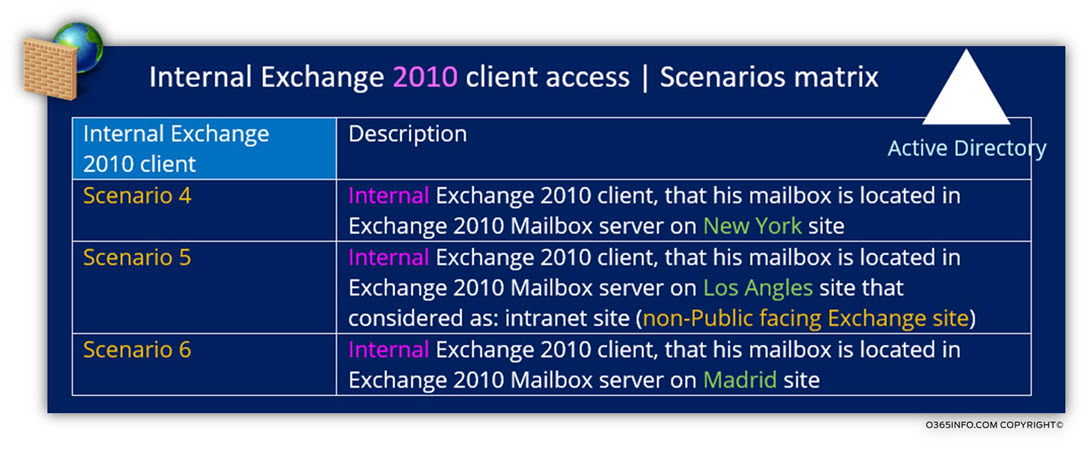
In the following diagram, we can see the representation of the different “internal client protocol connectivity flow” that can implement in the internal (non-pubic) Exchange environment.
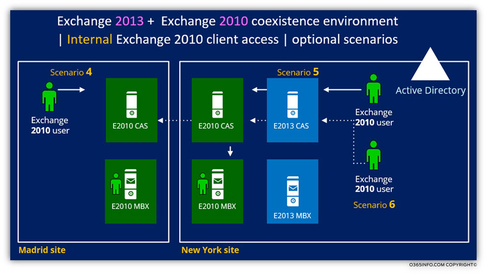
Scenario 4 – Exchange 2010 user, which his mailbox hosted on Exchange 2010 Mailbox server at the Madrid site.
The charter of this scenario is a company site that uses the Exchange 2010 legacy infrastructure and doesn’t include Exchange 2013 servers.
For the “Madrid Exchange 2010 clients”, the client protocol connectivity flow is implemented as a “combination” of the Exchange 2013 infrastructure and the local Exchange 2010 infrastructure.
- The Autodiscover service will be provided by the Exchange 2013 CAS (the Exchange 2013 CAS in the New York headquarters site).
- Madrid Exchange 2010 mail client such as Outlook, ActiveSync and OWA will access their “Exchange 2010 mailboxes” via local Exchange 2010 CAS.
- Web services for Exchange 2010 clients, such as Outlook, will be provided by the local Madrid Exchange 2010 CAS.
Scenario 5 – Exchange 2010 user, which his mailbox hosted on Exchange 2010 Mailbox server at the New York site.
- The Autodiscover service will be provided by the Exchange 2013 CAS.
- New York Exchange 2010 mail client such as Outlook, ActiveSync and OWA will access their “Exchange 2010 mailboxes” via local Exchange 2013 CAS that will proxy their requests to the local Exchange CAS 2010.
- Web services for Exchange 2010 clients, such as Outlook, will be provided by the local New York Exchange 2013 CAS.
Scenario 6 – Exchange 2010 user, which his mailbox hosted on Exchange 2010 Mailbox server at the Madrid site.
This scene looks identical to “Scenario 4” but the main difference is that the Exchange 2010 client physically located on the New York site.
When the Exchange 2010 client connects the Exchange CAS 2013 server in New York site, the Exchange CAS 2013 server recognizes that the user is an Exchange 2010 client and that his Exchange 2010 Mailbox server located on the Madrid site.
The Exchange CAS 2013 server will proxy the Exchange 2010 client to the “nearest Exchange 2010 CAS”. In our scenario, the Exchange 2010 CAS that located in New York site and the “New York Exchange 2010 CAS”, will proxy the request to the “Madrid Exchange 2010 CAS.”
What Others Are Reading
This Post Has 0 Comments